当我手上的新老锂电池越来越多的时候,我就很想组装一台机器来测定它们的电量了。于是就有了下面的玩意。
这台基于 AVR 单片机的简易锂电池电量计的测量原理很简单。锂离子电池的电量通常是指电池输出电压从充电限制电压(一般是 4.2V )下降到一个阈值(一般是 3.3V )的过程中所流过的总电荷量。事先测量好一只电阻的阻值然后将其作为待测电池的负载,并用 AVR 单片机内置的 ADC 测量其两端的电压,再将充满的待测电池连接至其两端即可达到目的。在这个过程中单片机通过累加每次取样的电流值(由 ADC 测量出的电压除以事先知道的阻值得出)和取样间隔时间的乘积得到电池的容量( mAh ),还可以通过累加电压 × 电流 × 取样间隔的值得到电池的总能量( Wh )。
这种简易电量计对电阻的要求比较高,首先电阻要有足够大的 PD ,然后它的温漂必须够小,最后阻值要合适,否则将会降低测量的精度。实际操作中要求电池电量计的误差在 3% 以下(否则按 10% 的误差,1000mAh 的测试结果范围达到了 900mAh – 1100 mAh ,完全无法接受)。因此为了方便阻值的准确测量并且保证电量的测量耗时不是太长(待测电池的电量要通过电阻放空),宜选用 20 – 50Ω 的电阻,并用精密的设备测量其阻值,精确到 0.1Ω 。有条件的话可以考虑专门的大功率低温漂电阻。在这里我使用的是一只标称 30Ω±5% 5W 的绕线电阻,并且事先借了 @zeroomega 同学的 FLUKE 万用表来测了下阻值,得到其常温下的阻值约为 30.3Ω ,在两端加了 5V 的电压之后温度升高,阻值变大,大约为 30.7Ω 。
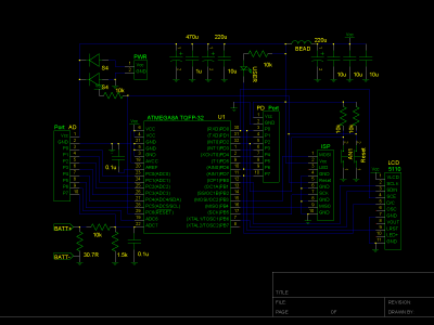
余下的部分主要是单片机和 LCD 显示屏,设备本身用另外的电源供电。板子图省事直接采用了网上买来的带 48 × 84 黑白点阵 LCD 的成品( LCD 驱动芯片为飞利浦的 PCD8544 ,也就是常说的 5110 液晶屏),单片机用的是 ATMEL 的 ATMEGA88PA (其实 ATMEGA48 应该就足够了),板子上设置了足够的电容来保持电压恒定,减小电源电压对单片机 ADC 误差的影响,同时防止干扰。
下面是电路示意图:
板子上有两个用于扩展的接口没有去掉。由于板子原本的设计用途与这里的不一样,所以电路部分稍作了修改。为了减小耗电量,延长电量计本身的电池寿命,我把电源指示灯以及 LCD 的背光去掉了,这在环境亮度尚可的情况下完全不影响屏幕的显示效果。虽然 ADC 对电压的采样频率被设置成了 4Hz ,但是 LCD 每秒钟仅更新一次,因为测试发现该 LCD 在更新时电流消耗非常大,降低 LCD 的更新频率能得到非常可观的节电效果。经过实验发现,这样做之后,整个设备的工作电流降到了 8mA 以下,用 1000mAh 的锂电池作为电源供电则至少可以运行 125 小时。单片机设置了 2.7V 的 BOD ( Brown-out Detection)。
在接上待测试电池后设备的工作指示灯以 2Hz 的频率闪烁,待测电池电压低于预先设定的阈值(即放电完成)后,工作指示灯熄灭。根据负载电池的电阻,测试时待测电池输出的电流约为 120mA ,这样对于容量约为 1000mAh 的锂电池完成一次测试约需要 8 个小时。于是,作为电源的电池一次充电大约可以测量 15 块电池(假定工作指示灯停止闪烁后你能及时更换待测试的电池或者关掉设备电源)。
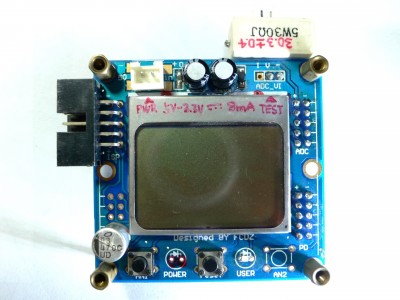
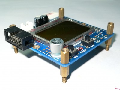
实物正面,左上方为连接设备电源的 HX2.54 接口,右上方为测试用的负载电阻以及用于连接待测电池的 HX2.54 接口。由于防呆槽的存在,一般情况下你不会把电池接反,而且就算接反由于后面有分压电阻和单片机本身的用于保护 I/O 口的二极管,电池也不会对单片机造成损伤。中间的黑白点阵 LCD 就不用多介绍了。左下方是个刷新屏幕的按钮,考虑到 LCD 的斑马线有接触不良导致花屏的可能所以设置了它(你总不想测量了 N 个小时之后却发现什么都读不出来吧?),中间的是个 RESET 按钮,右下方为黄色的工作指示灯。
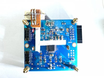
实物背面,主要是那只 ATMEL ATMEGA88PA 8 位 AVR 单片机。ADC 部分的走线贴上了绝缘胶带,以免灰尘和汗渍对其造成不良影响。接口和负载电阻被焊在了一个单独的万用板上,万用板和主板通过排针连接。
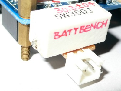
接口部分特写,负载电阻离接口尽量地近,尽量减少测试电流在线路上产生的分压,提高 Wh 数的测量精度。
板子以铜六角四个支撑,以便使用;保留了 ISP 接口,可以随时修改程序。
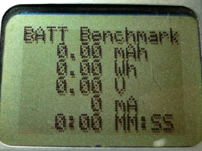
复位后的显示。使用时先将待测电池完全充满,然后连接上电量计的电源,再将待测电池连接在测试接口上,黄灯开始闪烁,测试就开始了。等到黄灯不再闪烁后测试完成,屏幕上显示的 mAh 和 Wh 信息为电池的容量。
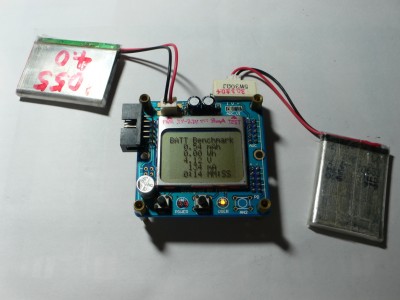
Battery benchmark in Action!
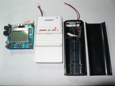
为了方便使用,你还需要一些夹具。你可以用废弃的万能充外壳来做手机电池的夹具(俺买品胜的这个傻充就是为了这个壳子,不过事后一想完全可以去批一堆山寨货回来嘛),或者淘个 18650 电池盒,加上废电池里面拆下来的保护板组成一个 18650 电芯测试座(注意这里一定需要保护板,否则电芯会过放,造成永久的损伤)。之前的《坏掉的 Acer AS4741G 电池拆解与分析》就是用这套东西完成的。
至于这玩意准不准,我倒是想办法做了点实验。由于没有别的专业设备,我只能通过 Nokia 6120c 上的 Energy Profiler 以及一只 Nokia 原装的 BL-5B 来验证了。根据几次测试的结果,自制的电量计跟 Nokia Energy Profiler 得出的结果没有明显的出入(最多 20 mAh / 890mAh )。另外,对于一些品牌的全新电池,这只电量计测得的容量和标称值接近,而且多次测量后结果没有很大的浮动,所以可以暂时认为这东西是比较靠谱的。
这机器的误差主要跟负载电阻的阻值以及单片机片上的 RC 时钟源的温漂有关,而这两者主要跟环境温度有关系。所以,如果可能的话可以考虑在温度恒定的环境下测试。由于板子本身的 IO 口分配,在这块板子上没办法使用低温漂的晶体振荡器。
最后,奉上单片机里面的代码。为了偷懒,按键用中断处理了,但是实际上你应该在程序主循环里面处理它。另外同样为了偷懒,在这里我用了 sprintf ,如果你能花时间自己构建一些简单的字符串格式化函数,那么你的目标代码将比我的小得多(我的约为 4.5KB )。当然,最后仍然是为了偷懒,我把函数体直接写在了头文件里,这样是不对的,请勿模仿。
主程序:battbench.c
这里用了一系列 MEGA88PA 里面特有的功能来完成电源管理,减小功率。老一点的 MEGA8 可能没有这些功能。
#include "include/adc.h"
#include "include/lcdascii.h"
#include "include/intandled.h"
#include "include/common.h"
#include <avr/power.h>
#include <avr/wdt.h>
#include <stdio.h>

/* TODO:
 * 1. Add BATT selection(4.2 - 3.3V, 4.2 - 2.7V, 1.4 - 0.9V)
 * 2. Add RLOAD settings
 */

/* Current load: 30.7 ohm @ working temp */
#define RLOAD 30700 /* Load resistance, mohm */
#define VMIN 3299   /* Stop at voltage, mv   */
#define MFREQ 4     /* Sampling rate,   Hz   */

volatile uint8_t updinf;
uint32_t mas = 0;
uint32_t mws = 0;
uint32_t adcmv = 0;
char strbuf[LCD_WCOL + 1];
uint32_t tcount = 0;
uint8_t intcyc = 0;

void update_info(void) {
  updinf = 1;
  LCD_write_english_string(0, 0, "BATT Benchmark");
  /* dmah = mas / 3600 * 10 = mas / 360 */
  sprintf(strbuf, "%4lu.%02lu mAh", (mas / 36) / 100, (mas / 36) % 100);
  LCD_write_english_string(0, 1, strbuf);
  sprintf(strbuf, "%4lu.%02lu Wh", (mws / 3600) / 1000, ((mws / 3600) % 1000) / 10);
  LCD_write_english_string(0, 2, strbuf);
  sprintf(strbuf, "%4lu.%02lu V", adcmv / 1000, (adcmv % 1000) / 10);
  LCD_write_english_string(0, 3, strbuf);
  sprintf(strbuf, "%7lu mA", (adcmv * 1000) / RLOAD);
  LCD_write_english_string(0, 4, strbuf);
  sprintf(strbuf, "%4lu:%02lu MM:SS", tcount / (4 * 60), (tcount % (4 * 60)) / 4);
  LCD_write_english_string(0, 5, strbuf);
  updinf = 0;
}

EMPTY_INTERRUPT(INT1_vect)

ISR(INT0_vect) {
  /* provides a way to recover LCD in case it is messed up */
  if(updinf == 0) LCD_init(); /* re-initialize LCD as user request */
}

ISR(TIMER1_COMPA_vect) {
  adcmv = ADC_read_mvolts();
  if(adcmv > VMIN) {
    mas += (adcmv * (1000 / MFREQ)) / RLOAD;
    mws += ((adcmv * adcmv) / RLOAD) / MFREQ;
    tcount++;
  }
  intcyc++;
  if(intcyc % MFREQ == 0) update_info();
  if(intcyc % 2 == 0 && adcmv > VMIN) LED_ON();
  else LED_OFF();
}

int main(void) {
  LCD_init();
  KL_init();
  power_timer0_disable();
  power_timer2_disable();
  power_twi_disable();
  power_usart0_disable();
  wdt_disable();
  ADC_init_ch(7); /* ADC7 is specially designed for battery voltage measurement */
  update_info();
  cli();
  SETBIT(TCCR1B, CS12);  /* set timer prescaler to 256 */
  SETBIT(TCCR1B, WGM12); /* waveform configuration */
  OCR1A = (uint16_t)(F_CPU / (MFREQ * 256));
  SETBIT(TIMSK1, OCIE1A); /* Output Compare Interrupt Enable (timer 1, OCR1A) */
  _delay_ms(500);
  sei(); /* Set Enable Interrupts */
  while(1);
  return 0;
}
ADC 函数库:include/adc.h
#ifndef __ADC_H__
#define __ADC_H__

#include "include/common.h"
#include <avr/interrupt.h>

#define ADC0 0b000
#define ADC1 0b001
#define ADC2 0b010
#define ADC3 0b011
#define ADC4 0b100
#define ADC5 0b101
#define ADC6 0b110
#define ADC7 0b111
#define AVREF 1100 /* In mini-volts */

/* Function declarations */
void ADC_init(void);
void ADC_init_ch(uint8_t channel);
uint16_t ADC_read_raw(void);
uint16_t ADC_read_mvolts(void);
uint16_t ADC_read_ch(uint8_t ch);

/* Functions */

/**********************************
 * ADC_init:
 *   Initialize ADC with selected
 *   channel. Can also be used to
 *   switch between channels.
 * Parameters:
 *   channel: Select ADC 0 - 7
 * Range:
 *   channel: 0 - 7
 *********************************/
void ADC_init_ch(uint8_t channel) {
  // If channel is valid we should switch to it and continue
  if(channel > 7) return;
  cli();
  CLEARBIT(ADCSRA, ADEN);
  ADMUX |= channel;

  // Internal 2.65V reference with capacitor on pin AVref enabled
  SETBIT(ADMUX, REFS0);
  SETBIT(ADMUX, REFS1);

  // Clock / 128 speed for highest accuracy
  SETBIT(ADCSRA, ADPS0);
  SETBIT(ADCSRA, ADPS1);
  SETBIT(ADCSRA, ADPS2);

  // Enable ADC
  SETBIT(ADCSRA, ADEN);

  // Reset ADC
  CLEARBIT(ADCSRA, ADIE);
  CLEARBIT(ADCSRA, ADIF);
  CLEARBIT(ADCSRA, ADSC);

  sei();
}

void ADC_init(void) {
  // Internal 2.65V reference with capacitor on pin AVref enabled
  SETBIT(ADMUX, REFS0);
  SETBIT(ADMUX, REFS1);

  // Clock / 128 speed for highest accuracy
  SETBIT(ADCSRA, ADPS0);
  SETBIT(ADCSRA, ADPS1);
  SETBIT(ADCSRA, ADPS2);

  // Enable ADC
  SETBIT(ADCSRA, ADEN);
}

uint16_t ADC_read_raw(void) {
  SETBIT(ADCSRA, ADSC);
  while(CHECKBIT(ADCSRA, ADIF) == 0);
  return ADC;
}

uint16_t ADC_read_mvolts(void) {
  uint16_t adcr = ADC_read_raw();
  if((ADMUX & 7) == 7) {
    adcr = (((uint32_t)adcr) * AVREF) >> 7;
    adcr -= adcr >> 4;
    adcr -= adcr >> 6;
    adcr -= adcr >> 7;
  }
  else adcr = (((uint32_t)adcr) * AVREF) >> 10;
  adcr += adcr / 20; /* Simple but effective calibration */
  return adcr;
}

uint16_t ADC_read_ch(uint8_t ch) {
  /* Select ADC Channel ch must be 0 - 7 */
  ch &= 0b00000111;
  ADMUX &= 0b11100000;
  SETV(ADMUX, ch);

  /* Start Single conversion */
  SETBIT(ADCSRA, ADSC);

  /* Wait for conversion to complete */
  while(!(CHECKBIT(ADCSRA, ADIF)));

  /***********************************
   * Clear ADIF by writing one to it
   * Note you may be wondering why we have write one to clear it
   * This is standard way of clearing bits in io as said in datasheets.
   * The code writes '1' but it result in setting bit to '0' !!!
   ***********************************/
  SETBIT(ADCSRA, ADIF);

  return(ADC);
}

#endif /* __ADC_H__ */
通用宏库:include/common.h
#ifndef __M85110_COMMON_H__
#define __M85110_COMMON_H__

/* Includes */
#include <avr/io.h>
/* #include <avr/pgmspace.h> in case that program needs to read itself. */
#include <util/delay.h>

/* Macros */
#define BIT7 0x80
#define BIT6 0x40
#define BIT5 0x20
#define BIT4 0x10
#define BIT3 0x08
#define BIT2 0x04
#define BIT1 0x02
#define BIT0 0x01
#define BIT(x) (1 << (x))
#define SETBIT(x, y) (x |= BIT(y))
#define CLEARBIT(x, y) (x &= ~ BIT(y))
#define CHECKBIT(x, y) (x & BIT(y))
#define SETV(x, y) (x |= y)
#define CLEARV(x, y) (x &= ~y)
#define CHECKV(x, y) (x & y)
#define SLEEP() asm("sleep")

#endif /* __M85110_COMMON_H__ */
中断、按键与指示灯函数库:include/intandled.h
#ifndef __INTnLED_H__
#define __INTnLED_H__

#include "include/common.h"
#include <avr/interrupt.h>

/* IO pins setup  */
#define IOPORT PORTD
#define IODIR DDRD
#define INT_0 2
#define INT_1 3
#define LED_USER 6

/* Macros */
#define LED_ON() (CLEARBIT(PORTD, LED_USER))
#define LED_OFF() (SETBIT(PORTD, LED_USER))

#ifndef INT_EXCEPTION_HANDLER
EMPTY_INTERRUPT(__vector_default)
#endif

void KL_init(void) {
  cli();

  /* Internal resistor / Charge before input */
  SETBIT(IOPORT, INT_0);
  SETBIT(IOPORT, INT_1);

  /* Charge the de-bounce capacitor */
  /* t = RC = 20kohm * 10uF = 200ms */
  /* When IO port is configured as  */
  /* Output, Ro is not known.       */
  _delay_ms(10);

  /* Set input mode */
  CLEARBIT(IODIR, INT_0);
  CLEARBIT(IODIR, INT_1);

  /* LED output */
  SETBIT(IODIR, LED_USER);
  LED_ON();

  /* Rising-edge-triggered INT0 and INT1 */
  SETBIT(EICRA, ISC00);
  SETBIT(EICRA, ISC10);
  SETBIT(EICRA, ISC01);
  SETBIT(EICRA, ISC11);

  /* Enable INT0 and INT1 */
  SETBIT(EIMSK, INT0);
  SETBIT(EIMSK, INT1);

  sei();
}

#endif /* __INTnLED_H__ */
LCD 字体和渲染函数库:include/lcdascii.h
#ifndef __LCD_ASCII_H__
#define __LCD_ASCII_H__

#include "include/common.h"
#include "include/pcd8544.h"
#include <avr/pgmspace.h>

/**********************************
 * 6 x 8 font
 * 1 pixel space at left and bottom
 * index = ASCII - 32
 **********************************/

const uint8_t asciifont[][6] PROGMEM = {
  { 0x00, 0x00, 0x00, 0x00, 0x00, 0x00 }, /* ' ' */
  { 0x00, 0x00, 0x00, 0x2f, 0x00, 0x00 }, /* '!' */
  { 0x00, 0x00, 0x07, 0x00, 0x07, 0x00 }, /* '"' */
  { 0x00, 0x14, 0x7f, 0x14, 0x7f, 0x14 }, /* '#' */
  { 0x00, 0x24, 0x2a, 0x7f, 0x2a, 0x12 }, /* '$' */
  { 0x00, 0x62, 0x64, 0x08, 0x13, 0x23 }, /* '%' */
  { 0x00, 0x36, 0x49, 0x55, 0x22, 0x50 }, /* '&' */
  { 0x00, 0x00, 0x05, 0x03, 0x00, 0x00 }, /* ''' */
  { 0x00, 0x00, 0x1c, 0x22, 0x41, 0x00 }, /* '(' */
  { 0x00, 0x00, 0x41, 0x22, 0x1c, 0x00 }, /* ')' */
  { 0x00, 0x14, 0x08, 0x3E, 0x08, 0x14 }, /* '*' */
  { 0x00, 0x08, 0x08, 0x3E, 0x08, 0x08 }, /* '+' */
  { 0x00, 0x00, 0x00, 0x50, 0x30, 0x00 }, /* ',' */
  { 0x00, 0x08, 0x08, 0x08, 0x08, 0x08 }, /* '-' */
  { 0x00, 0x00, 0x60, 0x60, 0x00, 0x00 }, /* '.' */
  { 0x00, 0x20, 0x10, 0x08, 0x04, 0x02 }, /* '/' */
  { 0x00, 0x3E, 0x51, 0x49, 0x45, 0x3E }, /* '0' */
  { 0x00, 0x00, 0x42, 0x7F, 0x40, 0x00 }, /* '1' */
  { 0x00, 0x42, 0x61, 0x51, 0x49, 0x46 }, /* '2' */
  { 0x00, 0x21, 0x41, 0x45, 0x4B, 0x31 }, /* '3' */
  { 0x00, 0x18, 0x14, 0x12, 0x7F, 0x10 }, /* '4' */
  { 0x00, 0x27, 0x45, 0x45, 0x45, 0x39 }, /* '5' */
  { 0x00, 0x3C, 0x4A, 0x49, 0x49, 0x30 }, /* '6' */
  { 0x00, 0x01, 0x71, 0x09, 0x05, 0x03 }, /* '7' */
  { 0x00, 0x36, 0x49, 0x49, 0x49, 0x36 }, /* '8' */
  { 0x00, 0x06, 0x49, 0x49, 0x29, 0x1E }, /* '9' */
  { 0x00, 0x00, 0x36, 0x36, 0x00, 0x00 }, /* ':' */
  { 0x00, 0x00, 0x56, 0x36, 0x00, 0x00 }, /* ';' */
  { 0x00, 0x08, 0x14, 0x22, 0x41, 0x00 }, /* '<' */
  { 0x00, 0x14, 0x14, 0x14, 0x14, 0x14 }, /* '=' */
  { 0x00, 0x00, 0x41, 0x22, 0x14, 0x08 }, /* '>' */
  { 0x00, 0x02, 0x01, 0x51, 0x09, 0x06 }, /* '?' */
  { 0x00, 0x3E, 0x41, 0x4D, 0x52, 0x5E }, /* '@' */
  { 0x00, 0x7C, 0x12, 0x11, 0x12, 0x7C }, /* 'A' */
  { 0x00, 0x7F, 0x49, 0x49, 0x49, 0x36 }, /* 'B' */
  { 0x00, 0x3E, 0x41, 0x41, 0x41, 0x22 }, /* 'C' */
  { 0x00, 0x7F, 0x41, 0x41, 0x22, 0x1C }, /* 'D' */
  { 0x00, 0x7F, 0x49, 0x49, 0x49, 0x41 }, /* 'E' */
  { 0x00, 0x7F, 0x09, 0x09, 0x09, 0x01 }, /* 'F' */
  { 0x00, 0x3E, 0x41, 0x49, 0x49, 0x7A }, /* 'G' */
  { 0x00, 0x7F, 0x08, 0x08, 0x08, 0x7F }, /* 'H' */
  { 0x00, 0x00, 0x41, 0x7F, 0x41, 0x00 }, /* 'I' */
  { 0x00, 0x20, 0x40, 0x41, 0x3F, 0x01 }, /* 'J' */
  { 0x00, 0x7F, 0x08, 0x14, 0x22, 0x41 }, /* 'K' */
  { 0x00, 0x7F, 0x40, 0x40, 0x40, 0x40 }, /* 'L' */
  { 0x00, 0x7F, 0x02, 0x0C, 0x02, 0x7F }, /* 'M' */
  { 0x00, 0x7F, 0x04, 0x08, 0x10, 0x7F }, /* 'N' */
  { 0x00, 0x3E, 0x41, 0x41, 0x41, 0x3E }, /* 'O' */
  { 0x00, 0x7F, 0x09, 0x09, 0x09, 0x06 }, /* 'P' */
  { 0x00, 0x3E, 0x41, 0x51, 0x21, 0x5E }, /* 'Q' */
  { 0x00, 0x7F, 0x09, 0x19, 0x29, 0x46 }, /* 'R' */
  { 0x00, 0x46, 0x49, 0x49, 0x49, 0x31 }, /* 'S' */
  { 0x00, 0x01, 0x01, 0x7F, 0x01, 0x01 }, /* 'T' */
  { 0x00, 0x3F, 0x40, 0x40, 0x40, 0x3F }, /* 'U' */
  { 0x00, 0x1F, 0x20, 0x40, 0x20, 0x1F }, /* 'V' */
  { 0x00, 0x3F, 0x40, 0x38, 0x40, 0x3F }, /* 'W' */
  { 0x00, 0x63, 0x14, 0x08, 0x14, 0x63 }, /* 'X' */
  { 0x00, 0x07, 0x08, 0x70, 0x08, 0x07 }, /* 'Y' */
  { 0x00, 0x61, 0x51, 0x49, 0x45, 0x43 }, /* 'Z' */
  { 0x00, 0x00, 0x7F, 0x41, 0x41, 0x00 }, /* '[' */
  { 0x00, 0x02, 0x04, 0x08, 0x10, 0x20 }, /* '\' */
  { 0x00, 0x00, 0x41, 0x41, 0x7F, 0x00 }, /* ']' */
  { 0x00, 0x04, 0x02, 0x01, 0x02, 0x04 }, /* '^' */
  { 0x00, 0x40, 0x40, 0x40, 0x40, 0x40 }, /* '_' */
  { 0x00, 0x00, 0x01, 0x02, 0x04, 0x00 }, /* '`' */
  { 0x00, 0x20, 0x54, 0x54, 0x54, 0x78 }, /* 'a' */
  { 0x00, 0x7F, 0x48, 0x44, 0x44, 0x38 }, /* 'b' */
  { 0x00, 0x38, 0x44, 0x44, 0x44, 0x20 }, /* 'c' */
  { 0x00, 0x38, 0x44, 0x44, 0x48, 0x7F }, /* 'd' */
  { 0x00, 0x38, 0x54, 0x54, 0x54, 0x18 }, /* 'e' */
  { 0x00, 0x08, 0x7E, 0x09, 0x01, 0x02 }, /* 'f' */
  { 0x00, 0x0C, 0x52, 0x52, 0x52, 0x3E }, /* 'g' */
  { 0x00, 0x7F, 0x08, 0x04, 0x04, 0x78 }, /* 'h' */
  { 0x00, 0x00, 0x44, 0x7D, 0x40, 0x00 }, /* 'i' */
  { 0x00, 0x20, 0x40, 0x44, 0x3D, 0x00 }, /* 'j' */
  { 0x00, 0x7F, 0x10, 0x28, 0x44, 0x00 }, /* 'k' */
  { 0x00, 0x00, 0x41, 0x7F, 0x40, 0x00 }, /* 'l' */
  { 0x00, 0x7C, 0x04, 0x18, 0x04, 0x78 }, /* 'm' */
  { 0x00, 0x7C, 0x08, 0x04, 0x04, 0x78 }, /* 'n' */
  { 0x00, 0x38, 0x44, 0x44, 0x44, 0x38 }, /* 'o' */
  { 0x00, 0x7E, 0x14, 0x12, 0x12, 0x0C }, /* 'p' */
  { 0x00, 0x0C, 0x12, 0x12, 0x0A, 0x7E }, /* 'q' */
  { 0x00, 0x7C, 0x08, 0x04, 0x04, 0x08 }, /* 'r' */
  { 0x00, 0x48, 0x54, 0x54, 0x54, 0x20 }, /* 's' */
  { 0x00, 0x04, 0x3F, 0x44, 0x40, 0x20 }, /* 't' */
  { 0x00, 0x3C, 0x40, 0x40, 0x20, 0x7C }, /* 'u' */
  { 0x00, 0x1C, 0x20, 0x40, 0x20, 0x1C }, /* 'v' */
  { 0x00, 0x3C, 0x40, 0x30, 0x40, 0x3C }, /* 'w' */
  { 0x00, 0x44, 0x28, 0x10, 0x28, 0x44 }, /* 'x' */
  { 0x00, 0x06, 0x48, 0x48, 0x44, 0x3E }, /* 'y' */
  { 0x00, 0x44, 0x64, 0x54, 0x4C, 0x44 }, /* 'z' */
  { 0x00, 0x08, 0x36, 0x41, 0x41, 0x00 }, /* '{' */
  { 0x00, 0x00, 0x00, 0x7F, 0x00, 0x00 }, /* '|' */
  { 0x00, 0x41, 0x41, 0x36, 0x08, 0x00 }, /* '}' */
  { 0x04, 0x02, 0x02, 0x04, 0x04, 0x02 }, /* '~' */
};

PGM_P font6x8 PROGMEM = asciifont;

/* Function declarations */
void LCD_write_char(uint8_t c);
void LCD_write_english_string(uint8_t X, uint8_t Y, char *s);

/* Functions */

void LCD_write_char(uint8_t c) {
  c -= 32;
  LCD_write_byte(pgm_read_byte(font6x8 + c * 6), 1);
  LCD_write_byte(pgm_read_byte(font6x8 + c * 6 + 1), 1);
  LCD_write_byte(pgm_read_byte(font6x8 + c * 6 + 2), 1);
  LCD_write_byte(pgm_read_byte(font6x8 + c * 6 + 3), 1);
  LCD_write_byte(pgm_read_byte(font6x8 + c * 6 + 4), 1);
  LCD_write_byte(pgm_read_byte(font6x8 + c * 6 + 5), 1);
}

/**********************************
 * LCD_write_english_String:
 *   This function prints English
 *   (ASCII) strings on LCD, single
 *   line only.
 * Parameters:
 *   *s: The string.
 *   X, Y: Position of the string.
 * Range:
 *   X: 0 - 83
 *   Y: 0 - 5
 *********************************/
void LCD_write_english_string(uint8_t X, uint8_t Y, char *s) {
  LCD_set_XY(X, Y);
  while (*s) {
    LCD_write_char(*s);
    s++;
  }
}

#endif /* __LCD_ASCII_H__ */
LCD 显示屏驱动函数库:include/pcd8544.h
#ifndef __PCD8544_H__
#define __PCD8544_H__

#include "include/common.h"

/* IO pins defination */
#define LCD_PORT PORTB
#define LCD_DIR DDRB
#define LCD_IN PINB
#define SCLK 0
#define SDIN 6
#define LCD_DC 7

#define LCD_PORT_AUX PORTD
#define LCD_DIR_AUX DDRD
#define LCD_IN_AUX PIND
#define LCD_CE 0
#define LCD_RST 1

/* LCD Size and ASCII Information */
#define LCD_ROW 84
#define LCD_LINE 48
#define LCD_WLN 6
#define LCD_WCOL 14
#define LCD_RAM ((LCD_ROW * LCD_LINE) / 8)
#define LCD_WORDS (LCD_WLN * LCD_WCOL)

/* Macros */
#define ENABLE_LCD() (SETBIT(LCD_PORT_AUX, LCD_CE))
#define DISABLE_LCD() (CLEARBIT(LCD_PORT_AUX, LCD_CE))

/* Function declarations */
void LCD_init(void);
void LCD_clear(void);
void LCD_set_XY(uint8_t x, uint8_t y);
void LCD_write_byte(uint8_t byte, uint8_t cmd);

/* Functions */

/**********************************
 * LCD_write_byte:
 *   Write data to LCD (Direct access)
 * Parameters:
 *   byte: The byte of data to write.
 *   cmd: Command mode true or false.
 *********************************/
void LCD_write_byte(uint8_t byte, uint8_t cmd) {
  unsigned char i;
  DISABLE_LCD();
  if(cmd == 0) CLEARBIT(LCD_PORT,LCD_DC); /* command mode, LCD_DC = 0 */
  else SETBIT(LCD_PORT, LCD_DC); /* data mode, LCD_DC = 1 */

  for(i = 0; i < 8; i++) {
    if(byte & 0x80) SETBIT(LCD_PORT, SDIN); /* SDIN = 1 */
    else CLEARBIT(LCD_PORT, SDIN); /* SDIN = 0 */

    CLEARBIT(LCD_PORT, SCLK); /* SCLK = 0 */
    byte = byte << 1;
    SETBIT(LCD_PORT, SCLK); /* SCLK = 1 */
  }

  ENABLE_LCD();
}

void LCD_clear(void) {
  unsigned int i;
  LCD_write_byte(0x0c, 0);
  LCD_write_byte(0x80, 0);
  for(i = 0; i < LCD_RAM; i++) LCD_write_byte(0, 1);
}

void LCD_set_XY(uint8_t X, uint8_t Y) {
  LCD_write_byte(0x40 | Y, 0); /* column */
  LCD_write_byte(0x80 | X, 0); /* row */
}

void LCD_init(void) {
  DDRB = 0xFF;
  PORTB = 0x3F;

  /* Switch to output */
  SETBIT(LCD_DIR, SCLK);
  SETBIT(LCD_DIR, SDIN);
  SETBIT(LCD_DIR, LCD_DC);
  SETBIT(LCD_DIR_AUX, LCD_CE);
  SETBIT(LCD_DIR_AUX, LCD_RST);

  /* Reset LCD with a low pulse */
  CLEARBIT(LCD_PORT_AUX, LCD_RST); /* LCD_RST = 0 */
  _delay_us(1);
  SETBIT(LCD_PORT_AUX, LCD_RST); /* LCD_RST = 1 */

  /* Disable and re-enable LCD */
  DISABLE_LCD();
  _delay_us(1);
  ENABLE_LCD();
  _delay_us(1);

  /* LCD Setup */
  LCD_write_byte(0x21, 0); /* Set LCD mode */
  LCD_write_byte(0xc8, 0); /* Set bias voltage */
  LCD_write_byte(0x06, 0); /* Thermal correction */
  LCD_write_byte(0x16, 0); /* 1:48 */
  LCD_write_byte(0x20, 0); /* Use basic commands */
  LCD_clear();
  LCD_write_byte(0x0c, 0); /* Normal mode */

  /* Disable LCD */
  DISABLE_LCD();
}

#endif /* __PCD8544_H__ */
编译脚本:Makefile
这里面包含了对应的熔丝位的设置,Makefile 的雏形来自于 ladyada 的 MiniPOV v2 项目。由于 avrdude 的数据库较老,里面没有 ATMEGA88PA 的信息,所以你需要把 avrdude.conf 里面有关 ATMEGA88 的部分复制一遍,并且修改 part id 、description 和 signature ,最后把修改过的版本跟 Makefile 置于同一目录。
MCU = atmega88p
F_CPU = 8000000   	# 8 MHz
AVRDUDE_PROGRAMMER = usbtiny

# Default target.
all: battbench.hex

# Program the device w/various programs

# this is necessary if you're burning the AVR for the first time...
# sets the proper fuse for 8MHz internal oscillator with no clk div
burn-fuse:
	$(AVRDUDE) $(AVRDUDE_FLAGS) -u -U lfuse:w:0xe2:m -U hfuse:w:0xdd:m -U efuse:w:0x01:m

# this programs the dependant hex file using our default avrdude flags
program: battbench.hex
	$(AVRDUDE) $(AVRDUDE_FLAGS) $(AVRDUDE_WRITE_FLASH)$<

FORMAT = ihex 		# create a .hex file

OPT = s			# assembly-level optimization

# Optional compiler flags.
#  -g:        generate debugging information (for GDB, or for COFF conversion)
#  -O*:       optimization level
#  -f...:     tuning, see gcc manual and avr-libc documentation
#  -Wall...:  warning level
#  -Wa,...:   tell GCC to pass this to the assembler.
#    -ahlms:  create assembler listing
CFLAGS = -g -O$(OPT) \
-funsigned-char -funsigned-bitfields -fpack-struct -fshort-enums \
-Wall -Wstrict-prototypes \
-DF_CPU=$(F_CPU) \
-Wa,-adhlns=$(<:.c=.lst) \
$(patsubst %,-I%,$(EXTRAINCDIRS)) \
-mmcu=$(MCU)

# Set a "language standard" compiler flag.
CFLAGS += -std=gnu99

# Optional assembler flags.
#  -Wa,...:   tell GCC to pass this to the assembler.
#  -ahlms:    create listing
#  -gstabs:   have the assembler create line number information; note that
#             for use in COFF files, additional information about filenames
#             and function names needs to be present in the assembler source
#             files -- see avr-libc docs [FIXME: not yet described there]
ASFLAGS = -Wa,-adhlns=$(<:.S=.lst),-gstabs

# Optional linker flags.
#  -Wl,...:   tell GCC to pass this to linker.
#  -Map:      create map file
#  --cref:    add cross reference to  map file
LDFLAGS = -Wl,-Map=$(TARGET).map,--cref

# avr-size flags.
#  -C:        friendly output
SIZEFLAGS = -C --mcu=$(MCU)

# ---------------------------------------------------------------------------
# Programming support using avrdude.
AVRDUDE = avrdude

AVRDUDE_WRITE_FLASH = -U flash:w:

AVRDUDE_FLAGS = -p $(MCU) -c $(AVRDUDE_PROGRAMMER) -C ./avrdude.conf

# ---------------------------------------------------------------------------
# Define directories, if needed.
DIRAVR = c:/winavr
DIRAVRBIN = $(DIRAVR)/bin
DIRAVRUTILS = $(DIRAVR)/utils/bin
DIRINC = .
DIRLIB = $(DIRAVR)/avr/lib

# Define programs and commands.
CC = avr-gcc
OBJCOPY = avr-objcopy
OBJDUMP = avr-objdump
SIZE = avr-size
REMOVE = rm -f

# Define all object files.
OBJ = $(SRC:.c=.o) $(ASRC:.S=.o)

# Define all listing files.
LST = $(ASRC:.S=.lst) $(SRC:.c=.lst)

# Combine all necessary flags and optional flags.
# Add target processor to flags.
ALL_CFLAGS = -I. $(CFLAGS)
ALL_ASFLAGS = -mmcu=$(MCU) -I. -x assembler-with-cpp $(ASFLAGS)

# Create final output files (.hex) from ELF output file.
%.hex: %.elf
	@$(OBJCOPY) -O $(FORMAT) -R .eeprom $< $@

# Link: create ELF output file from object files.
%.elf: %.o
	@$(CC) $(ALL_CFLAGS) $< --output $@ $(LDFLAGS)
	@$(SIZE) $(SIZEFLAGS) $@

# Compile: create object files from C source files.
%.o : %.c
	@$(CC) -c $(ALL_CFLAGS) $< -o $@

# Compile: create assembler files from C source files.
%.s : %.c
	@$(CC) -S $(ALL_CFLAGS) $< -o $@

# Assemble: create object files from assembler source files.
%.o : %.S
	@$(CC) -c $(ALL_ASFLAGS) $< -o $@

# Target: clean project.
clean:
	$(REMOVE) *.hex
	$(REMOVE) *.lst
	$(REMOVE) *.obj
	$(REMOVE) *.elf
	$(REMOVE) *.o

博主是做什么的啊?定期都有得东西拆拆。。。好羡慕哦
工科大学生。有些东西是之前拆的,建了 Blog 以后发上来而已。不过还是以建站之后拆的为主。
仔细看了一下,一个小东西也被博主设计得非常周到和用心。
就是搞不懂为什么要自己写Makefile ,用个编译器是不是更方便一点? 不过挺佩服博主电子的功底和兴趣的。
在 Windows 下可以用 IDE ,在 Linux 下比较习惯 Makefile 一点。
用中断不是挺好的吗?响应应该更快吧~
还是有些不太懂,不过本人水平也就这样了。。。
博主画sch的软件用的是哪个啊?
gschem
应该可以用低功耗模式省电,AT的叫sleep mode吧