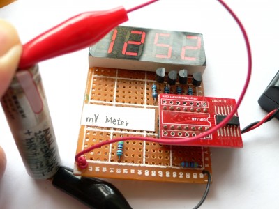
考虑到家里有大量不配对的干电池,每次把万用表带回去测量又不现实,另外买个万用表又有点浪费(其实不贵,但是邮费你可桑得起?),考虑到手头还有闲置的 ATTINY24A 单片机外加四位数码管,所以 DIY 一个也不是不行,于是开始动手。
先奉上电路图。
本着成本最低的原则,数码管的段用单片机的 PA0 – PA6 直接驱动( AVR 的 GPIO 能提供 20mA 的电流,木问题),由于电源是两节干电池(也就是 3V ),而且数码管是以扫描的方式间歇点亮的,所以不加电阻问题不大。
由于手头上四位的数码管是共阳极的,所以位驱动用 S9012 PNP 型 BJT 完成,这个管子可以提供最大 500mA 的电流,拿来点数码管完全足够。位驱动信号由单片机的 PB0 – PB3 输出。至于小数点,如果需要的话可以将数码管的 dp 段通过一个电阻和第一位的位驱动信号相连,这样第一位后面就会总是跟着一个小数点。
由于 ATTINY24A 内建的 ADC 参考电压是 1.1V ,所以这里将输入电压用 47.0kΩ 和 4.70kΩ 的精密电阻分压后由 PA7 输入给单片机内的 10 位 ADC 。这样量程 0.000V – 9.999V ,精度 = (47 + 4.7)/4.7 × 1.1 / 210 = 0.012V ,也就是说数码管最后一位示数实际无意义。同时由于单片机自身大电流驱动数码管会对模拟部分造成影响,所以后面在代码里有了四次采样取平均的超采样做法,消除干扰并尽可能地提升精度。输入电压在 10.000V – 12.100V 时可以显示超量程符号。
至此,单片机的 14 个引脚(包括两个电源脚)全部用完,就连复位脚所在的 PB3 都被当做 IO 给分配出去了。因此烧写程序之前一定要小心检查,否则一旦出错想再 ISP 就比较麻烦了,得保证单片机在编程时上电之前 RST 就已经拉低了。
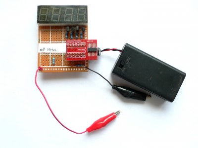
成品。
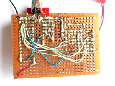
由于数码管的引脚比较乱,所以干脆不画板,直接全部飞线。
贴片的 ATTINY24A 要比直插的便宜不少,所以当时就买了贴片的芯片 + 转接板。缺点是体积有点大了。
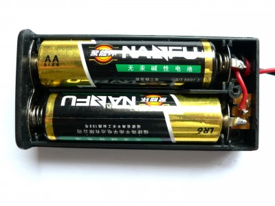
电源,电池盒自带了开关,这回又可以偷懒了。
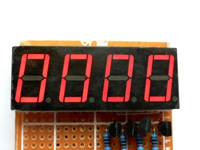
位驱动电路的三极管和电阻,貌似其中有一颗有点问题,或者是因为 RST 脚的问题(实际中 PB3 接了第三位,PB2 接了第四位),第三位总是比较暗。
按照设定,开机自检四位全部显示“ 8 ”,然后回零。
测试,效果还行。由于模拟电源和数字电源没分开(毕竟单片机的引脚就那么点),所以有抖动、轻微零偏的话都很正常,一般不会大到影响使用。
最后奉上代码,烧写之后记得把熔丝设置成「 lfuse:0xe2 hfuse:0x5e efuse:0xff 」。
#include <avr/io.h>
#include <util/delay.h>
#include <avr/interrupt.h>

#define REFRESH_RATE 500

// Display buffer.
uint8_t dispbuf[4] = {0x40, 0x40, 0x40, 0x40};
// Digit pointer.
uint8_t dispptr = 0;
// NOTICE: Be careful not to pull PA7 high since it is connected to ADC.
// This font is for common-anode segment displays.
uint8_t dispfont[] = {
  0x40, // "0"
  0x79, // "1"
  0x24, // "2"
  0x30, // "3"
  0x19, // "4"
  0x12, // "5"
  0x02, // "6"
  0x78, // "7"
  0x00, // "8"
  0x10, // "9"
  0x06, // "E"
  0x7f, // " "
};

#define BIT(x) (1 << (x))
#define SETBIT(x, y) (x |= BIT(y))
#define CLEARBIT(x, y) (x &= ~ BIT(y))
#define CHECKBIT(x, y) (x & BIT(y))

ISR(TIM1_COMPA_vect) {
  // Inverse all bits since "0" means that the digit is active.
  PORTB = ~(1 << dispptr);   PORTA = dispfont[dispbuf[dispptr]];   dispptr ++;   // Resetting the pointer is the most reasonable way to do it, though may not be the simplest.   if(dispptr == 4) dispptr = 0;   // Light the digit for 1800us then turn off.   _delay_us(1800);   PORTB = 0xff; } void adc_init(void) {   cli();   CLEARBIT(ADCSRA, ADEN);   // Single-end input from channel 7   ADMUX = 7;   // Internal 1.1V reference   CLEARBIT(ADMUX, REFS0);   SETBIT(ADMUX, REFS1);   // Clock / 128 speed   SETBIT(ADCSRA, ADPS0);   SETBIT(ADCSRA, ADPS1);   SETBIT(ADCSRA, ADPS2);   // Enable ADC   SETBIT(ADCSRA, ADEN);   // Reset ADC   CLEARBIT(ADCSRA, ADIE);   CLEARBIT(ADCSRA, ADIF);   CLEARBIT(ADCSRA, ADSC);   sei(); } uint16_t read_mv(void) {   // Start a conversion.   SETBIT(ADCSRA, ADSC);   // Wait for the conversion to complete and convert data in ADC register into mV value.   while(CHECKBIT(ADCSRA, ADIF) == 0);   return ((uint32_t)ADC * (1100 * 11) ) >> 10;
}

void print(uint16_t data) {
  // NOTICE: PB2 and PB3 are in reversed order.
  dispbuf[2] = data / 1000;

  // Report error if voltage exceeded the range.
  if(dispbuf[2] > 9) {
    dispbuf[2] = 10; // "E"
    dispbuf[3] = 11; // " "
    dispbuf[1] = 11; // " "
    dispbuf[0] = 11; // " "
    return;
  }

  // Put every digits into their positions.
  dispbuf[3] = (data % 1000) / 100;
  dispbuf[1] = (data % 100) / 10;
  dispbuf[0] = data % 10;
}

int main(void) {
  uint16_t avg;

  // IO ports setup.
  // PA7 is connected to ADC, configure it as an input pin and no pull-up.
  DDRA = 0x7f;
  DDRB = 0xff;

  // Light up all digits and segments for display testing.
  PORTA = 0x00;
  PORTB = 0x00;

  adc_init();

  // Timer and interrupt setup.
  SETBIT(TCCR1B, CS11);
  SETBIT(TCCR1B, WGM12);
  OCR1A = (uint16_t)(F_CPU / (REFRESH_RATE * 8));

  // Wait 500ms for display testing, then start display refreshing interrupt.
  _delay_ms(500);
  SETBIT(TIMSK1, OCIE1A);

  // Main loop
  while(1) {
    // Oversampling increases accuracy, thus makes last digit meaningful.
    // Delay values are not absolute: there are interrupts.
    _delay_ms(10);
    avg = read_mv();
    _delay_ms(10);
    avg += read_mv();
    _delay_ms(10);
    avg += read_mv();
    _delay_ms(10);
    avg += read_mv();
    print(avg >> 2);
  }
  return 0;
}


